Steel Pipe Drawing at GetDrawings Free download
The main purpose of a piping drawing is to communicate the information in a simple way. These drawings are schematic representations and they would define functional relationships in a piping system. The drawings would help to speed up the fabrication and erection work at the site.
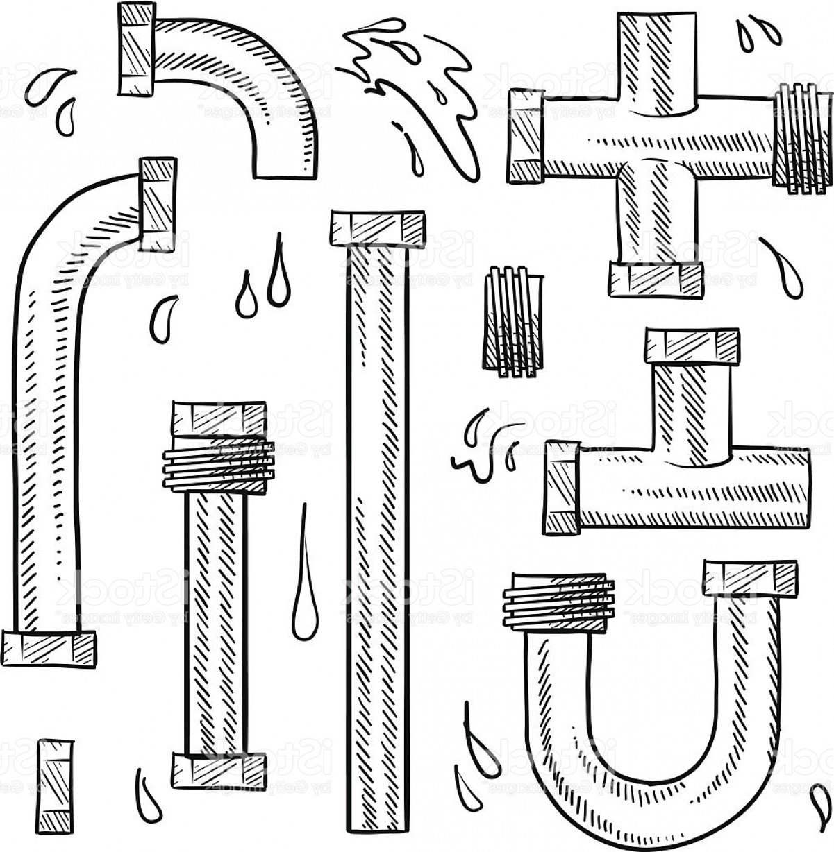
Pipe Sketch at Explore collection of Pipe Sketch
This video explain about Types of drawings used in piping projects.The main purpose of a technical drawing is to communicate fabrication requirements clearly.

How to Draw Isometric Pipe Drawings in Autocad Gautier Camonect
Piping and instrumentation diagram, also called P&ID, is a drawing in the process industry. It presents the interconnection of process equipment and the instrumentation which is used to control the process. And this kind of diagram is mainly used for laying out a process control installation.
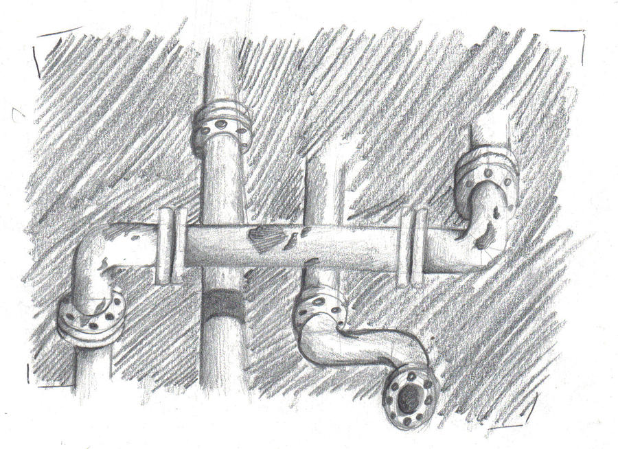
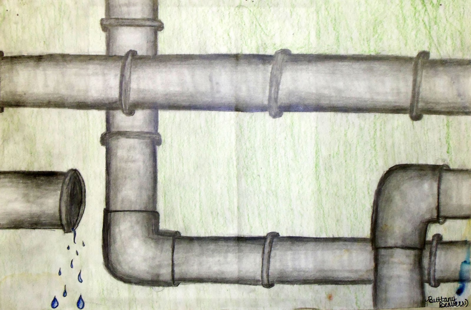
Pipe Sketch by GrieveC50 on DeviantArt
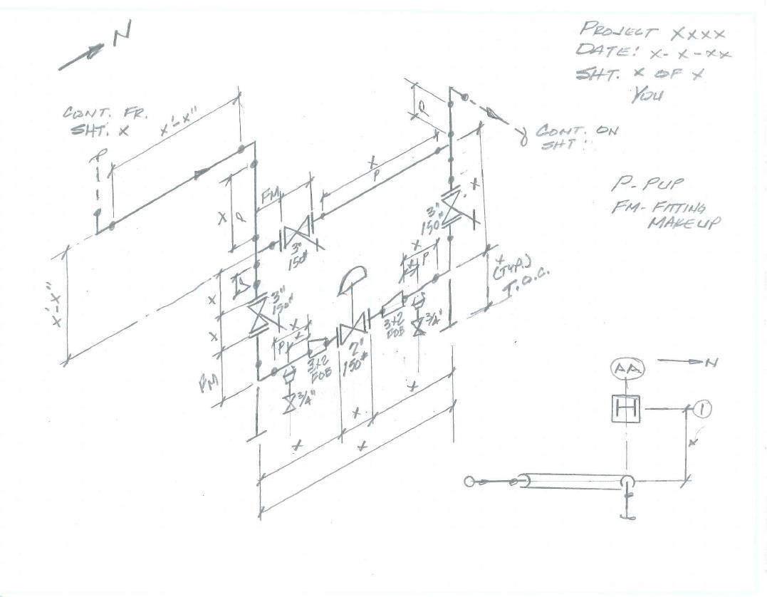
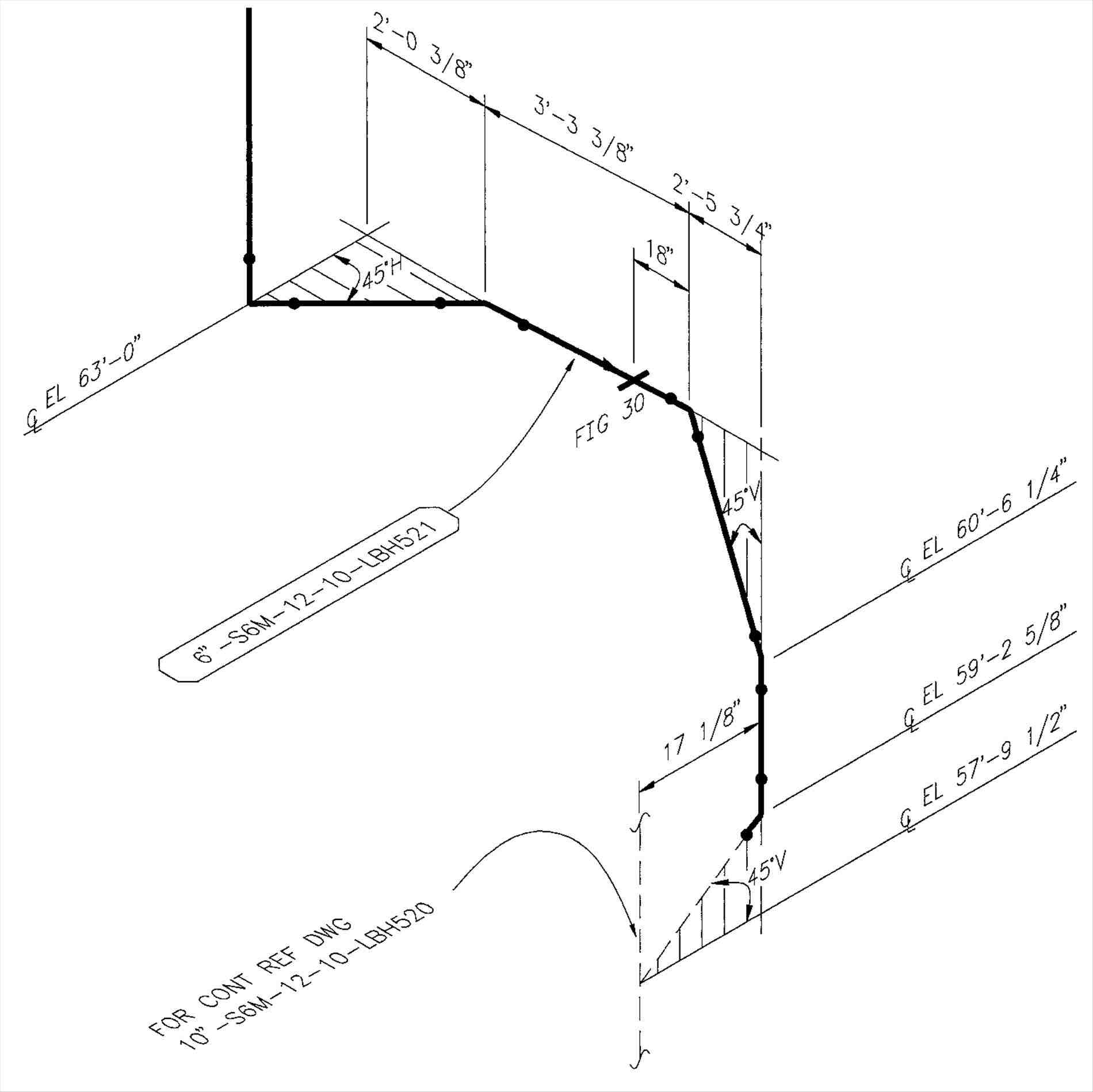
Pipe drawings differ from common blueprints one would see in the construction or welding field. The drawings we often see in these fields would be orthographic views which may include top, front, right side, left side, bottom, and back views depending on what is needed to convey information. Pipe drawings are presented in an Isometric view (ISO.)
How To Draw Isometric Drawing For Piping
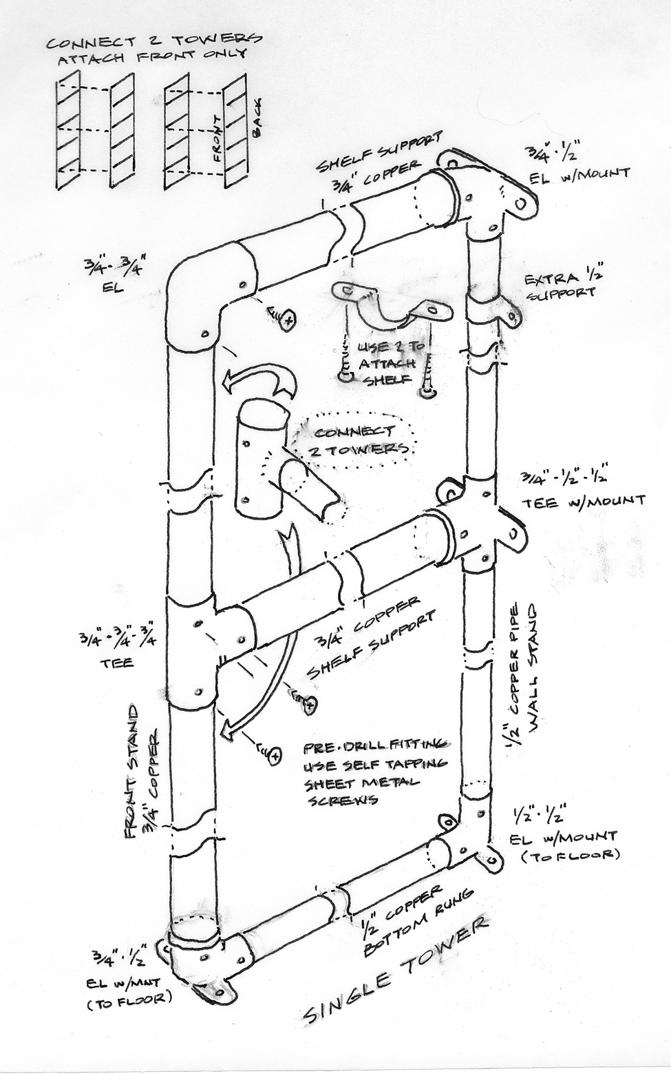
What is Piping Isometric drawing? The main body of a piping Isometric drawing is consist of: Section of Left or right of Piping Isometric drawing includes: Bottom Section of Isometric Drawing contains: Calculations for Piping data from Isometric drawing Features of Piping Isometric Drawings The coordinate system of Piping Isometric
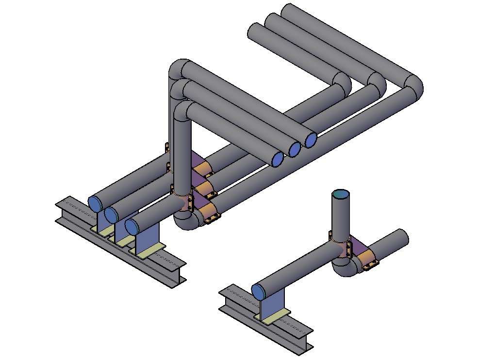
3D Pipe Drawing In AutoCAD File Cadbull
How to Draw a P&ID Online 1 List Elements that You Need Before sketching your P&ID, it's much better to make a list of all elements that you need. Usually include the necessary equipment like pipes, instruments, valves, control devices, pumps, etc. 2 Select P&ID Symbol Library
Isometric Piping Drawing Sketch Coloring Page
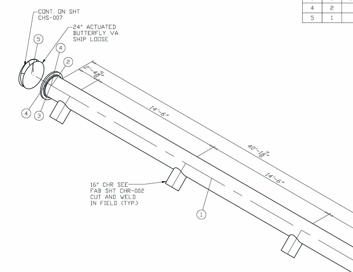
Pipes are drawn with a single line irrespective of the line sizes, as well as the other configurations such as reducers, flanges, and valves. Pipes are shown in the same size. The actual sizes are notified in the Bill of Material, tagging, call-out, or notes. A piping isometric drawing provides all the required information like: Pipe Line Number
Pipes Drawing at GetDrawings Free download
How to read piping isometric drawing symbols. Tutorial for fitters. @technicalstudies. Donate https://paypal.me/Technicalstudies502ALL VIDEOShttps://www.yo.
Pipes Drawing at GetDrawings Free download
13. Pipe Drawings. Pipe drawings differ from common blueprints one would see in the construction or welding field. The drawings we often see in these fields would be orthographic views which may include top, front, right side, left side, bottom, and back views depending on what is needed to convey information.

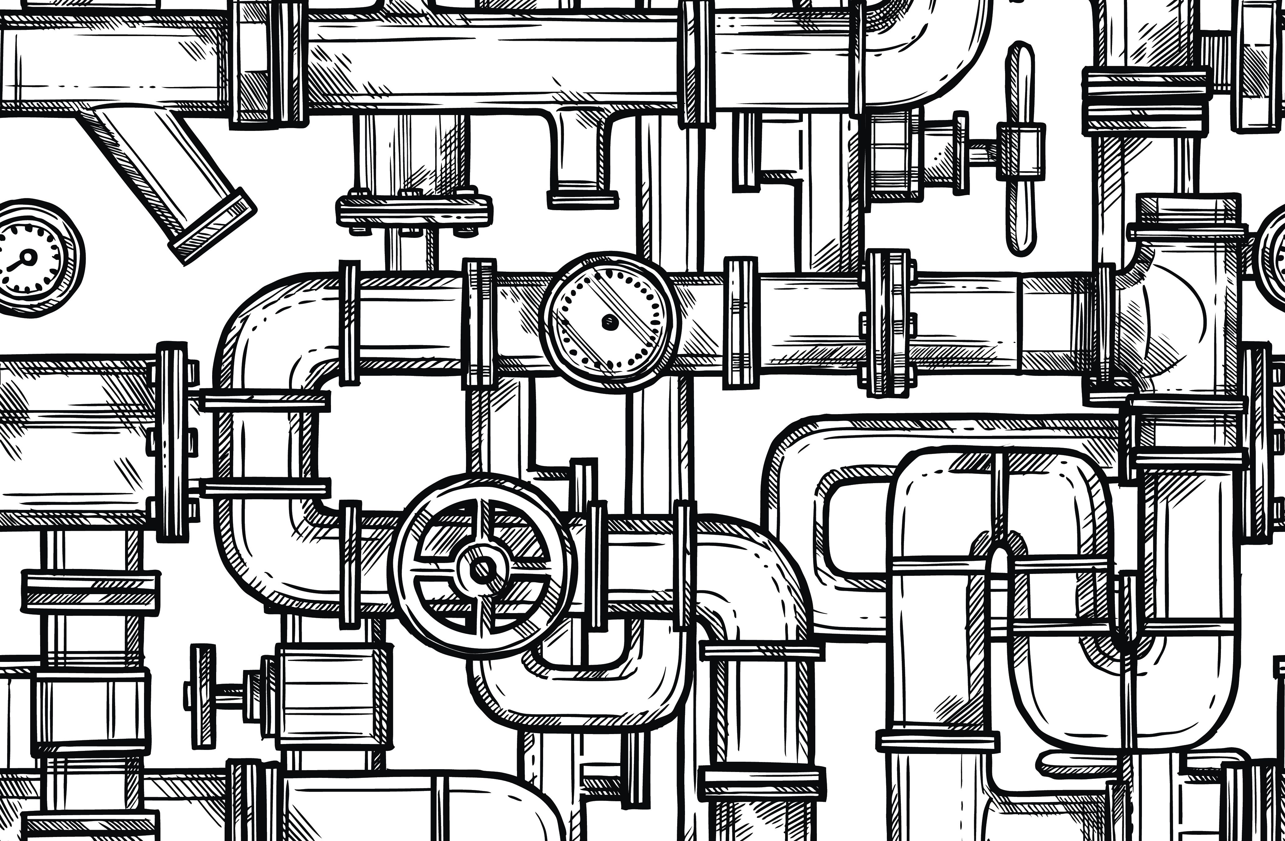
Steel Pipe Sketch Vector 167219191
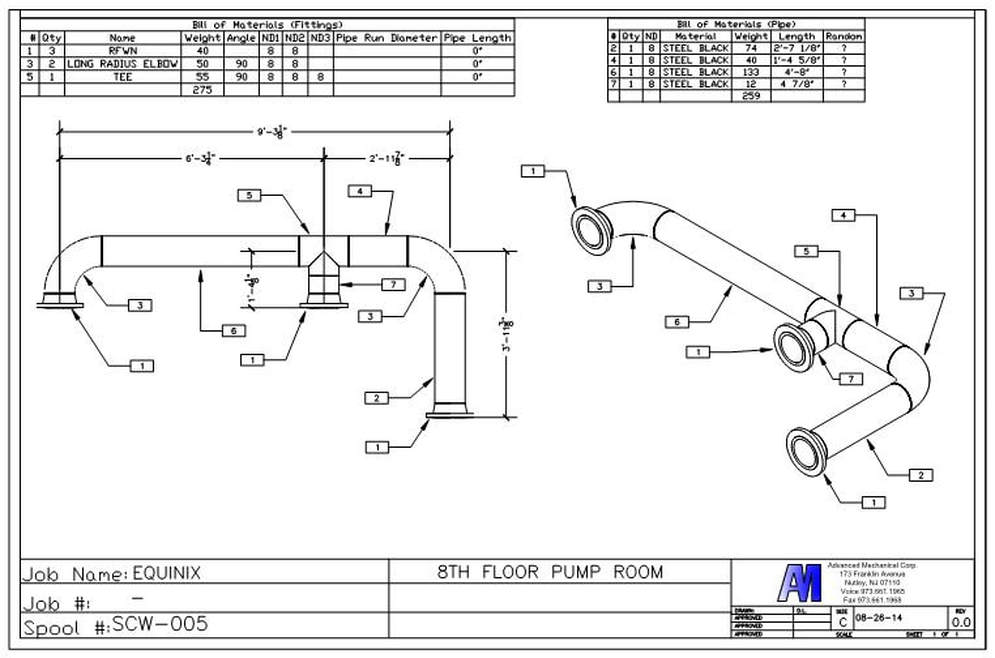
Easy Isometric is the first pipe isometric drawing app that helps users make detailed isometric drawings in the field and without the need for tedious reference materials. Automated Bill of Materials. No more tedious material tracking when creating a pipe isometric drawing. As you design fabrication level isometric drawings, Easy Isometric.
Pipe Drawing at GetDrawings Free download
Piping Isometric drawing is an isometric representation of single pipe line in a plant. It is the most important deliverable of piping engineering department. Piping fabrication work is based on isometric drawings. Piping isometric drawing consists of three sections. Main Graphic section consist of Isometric Representation of a pipe line route.

Pin on illustration Hand draw
Piping design and drafting services involve the creation of detailed drawings that serve as schematic representations depicting the functional relationships in a pipeline system. The primary purpose of these piping drawings is to communicate the construction and fabrication requirements in a simple manner. The drawings are done in such a way that even a non-technical person can comprehend.

How To Draw A Pipe
Pipeline drawings are vital graphical representations used in various industries, including engineering, construction, and non-destructive testing (NDT). They serve as precise illustrations providing essential information about the layout, dimensions, materials, and key components of a pipeline system.
Isometric Pipe Drawing at GetDrawings Free download
A piping isometric drawing is a technical drawing that depicts a pipe spool or a complete pipeline using an isometric representation. The drawing axes of the isometrics intersect at an angle of 60°.
Pipe Drawing at GetDrawings Free download
Piping drawings provide guidelines for to design and construction activities of piping items. In this article, we will explore the piping drawing basics for Engineering companies. Table of Contents Types of Piping Drawings Piping Plan Drawings/General Arrangement Drawings (GAD) Process Flow Diagrams (PFD) Piping & Instrumentation Diagram (P&ID)

Sketch Pipes System Sketches, Plumbing logo, Infographic inspiration
Another one! We are concluding our first Pipefitter series run with a video on how to draw isometric drawings. How to read ISO drawings. What are ISO drawing.